HydroSym Quick Start
HydroSym makes the drawing of schematics intuitive. Components and symbols can be selected from the well-stocked library, placed on a canvas and connected by smart connection lines.
The library
The library is found on the right-hand part of the screen. It is divided into three categories: Components, Components+, Symbols.
- Symbols are drawing objects without additional information.
- Components are symbols with meta-data such as manufacturer, data sheet, maximum pressure rating and type.
- Components+ combine often used together components into building blocks quickly drawing your schematic, for example a tank or a power pack.
See the HydroSym Tutorial - Symbols and components video for more information on how to make your own components and symbols.
Starting a new schematic
To start a new, empty schematic, press the button labelled New and select a template, or use the menu [File > New > Schematic].
Add components to the schematic
Open the Components tab in the Library panel. Enter the name of the component in the search field, or locate it by browsing the tree view. Place a component by dragging it onto the schematic, or double-clicking the component in the library and then placing it on the schematic. When a new component is placed, optionally an item number can be entered.
Drawing connection lines
Ports of components or symbols are connected with connection lines. Connection lines can also connect to other connection lines, or terminate at any position in the schematic. These three methods are described below. For a more in-depth explanation on connection lines see HydroSym Tutorial - Working with connection lines and HydroSym Tutorial - Useful options with connection lines.
Connection line between two ports
-
Press the shortcut C or click the
 icon in the left toolbar.
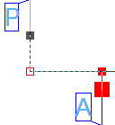
Next, select the two ports that need to be connected by the line.
A line will be suggested.
The left mouse button inserts the extra points that the line will call at, the right mouse button finalizes the line.
Note, HydroSym starts building the line from the point that was selected last.
This point is indicated by a red square (see image).
icon in the left toolbar.
Next, select the two ports that need to be connected by the line.
A line will be suggested.
The left mouse button inserts the extra points that the line will call at, the right mouse button finalizes the line.
Note, HydroSym starts building the line from the point that was selected last.
This point is indicated by a red square (see image). -
When two ports that are not horizontally or vertically aligned need to be connected by a straight line, they can be automatically aligned. First, select both ports, then press C. The first selected port will act as reference for the alignment.
Between a port and a connection line, or between two connection lines
-
To draw a line straight from a port to a connection line, press C, select the port and then click on a random point on the target connection line.
-
If the new connection line needs to originate from a specific point on an existing line, press C, select the point on the line and then select the port. Drawing a new connection line between two existing lines is done in the same way.
A connection line to a point on the schematic
- A connection line can terminate at an empty spot in the schematic. Press C, select a port or a specific point on a connection line as starting point, then navigate the pointer to the desired ending point and press the left mouse button while holding the [shift] key.
Tip
A slanted connection line can be drawn by pressing O to disable the Ortho function while drawing.
Tip
A component (like a hose) that is placed on a connection line will be inserted into this line automatically.
Selecting
Objects can be selected with the left mouse button. Hold Ctrl to add objects to a selection. A selection window can also be used: when it is dragged from right to left all objects that are entirely or partly enclosed in the window are selected. Dragging the window from left to right selects only the objects that are enclosed entirely within the window.
Moving
Selected objects can be moved around by ‘drag & drop’ with the arrow keys or by pressing the space bar. Pressing space while moving will rotate the objects 90 degrees.
Editing
The standard shortcuts ([Ctrl+C]{.keycombo}, [Ctrl+V]{.keycombo}, [Ctrl+Z]{.keycombo}) are available. The properties of a component can be edited by double clicking on it. Texts can be edited this way as well. A right click opens a pop-up menu with functions that depend on the number and type of the selected objects. For example, alignment will be available when multiple objects are selected. By clicking on it twice (but not double clicking) a symbol’s text can be moved without ungrouping the symbol.
Navigating
The scroll wheel zooms in and out. Press the [home] key to adjust the zoom level to show the entire schematic. Panning is done by holding the middle mouse button, or by pressing shift and the left mouse button simultaneously.
Bill of Materials
The bill of materials is automatically filled while placing components. It can be accessed and edited via the menu View>Bill of materials. It can be printed or exported to a file (pdf, dxf, dwg) with the print button and it can be placed on the schematic.